DISCLAIMER: This information is presented merely as a guide. Due to changes from year-to-year and options-to-options it may not be totally accurate. I can not be held responsible for anything that happens as a result of using this guide.
This is not something that should be attempted by someone who has never worked on a car, or has little experience with them.
If you use this guide, I only ask two things:
1. Accept the disclaimer,
2. Provide Feedback - comments/tips/problems/differences.
There, now that thats out of the way, lets begin.
Tools needed

- Jack
- Jackstands
- Transmission jack - I borrowed mine from my uncle, its from Sears, and has an angle adjuster and strap to keep the trans on the jack.
- Impact wrench
- 6mm allen socket
- 7mm allen socket
- 8mm allen socket
- 6mm allen wrench
- 8mm allen wrench
- 10mm socket (3/8" drive)
- 13mm socket (3/8" drive)
- 15mm shallow socket (3/8" drive)
- 15mm deep socket (3/8" drive)
- 15mm wrench
- 15mm "shorty" wrench
- 16mm shallow socket (3/8" drive)
- 16mm deep socket (3/8" drive)
- 16mm wrench
- 16mm "shorty" wrench
- 17mm shallow socket (3/8" drive)
- 17mm deep socket (3/8" drive)
- 17mm impact socket (1/2" drive)
- 17mm wrench
- 17mm "shorty" wrench
- 18mm wrench
- 22mm wrench
- 3/8" drive ratchet
- 12" extension w/swivel end
- 6" extension
- 3" extension
- screwdriver
- phillips screwdriver
- Torque wrench
- Plug for coolant hose (I used a 3/8" bolt)
- 6 point T40 Torx bit
- 12 point T40 Torx bit - special tool???
- Loc-Tite
- Patience
- Common Sense
- fan (gotta keep cool, right?)
If youre planning on changing the trans fluid, there are some special tools required. On my car it required a 17mm allen wrench (fill plug) and "3357 triple square socket" (drain plug) I bought the 3357 from http://www.zelenda.com and made the allen from a 17mm bolt welded to an old 1/2" drive socket.
I, of course, had these sitting in my toolbox, in the back of my car, 180 miles away :( So I made a new fill plug remover by welding a nut to bolt, and using a wrench on the nut, which turned the bolt, which turned the fill plug. I then picked the trans up and drained it through the fill plug. I used Redline MTL (75w90) fluid, it takes 2.9 quarts.
If you do change the fluid, do it after youre done. Wouldnt want to take the chance of spilling fluid in the area you will be working in/on for the next several hours.
Parts
- Flywheel
- Clutch
- Pressure plate
- Flywheel bolts (shorter than stock bolts)
- Pressure plate bolts (same as stock bolts)
- Throwout bearing
- Clutch alignment tool - not necessary, but helpful
- Driveaxle or driveshaft bolts - in case you muck up the ones you have.
- New lock-nuts for the turbo - Bentley manual says to replace them, I didnt
- New drive axle and driveshaft seals - Bentley manual says to replace them, I didnt
Instructions - Removal
I am following the Bentley manual for the most part. There are some steps I skipped, some that need to be added, and others that can be done differently. Im posting the steps and providing more info with them. If you are attempting this, you should have this manual already. It contains many other things, especially the required torque values for the bolts.
1. Disconnect ground cable from battery - 10mm
2. Remove driveshaft - ignore this step, its not necessary
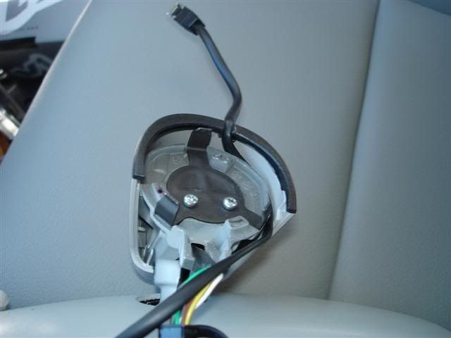
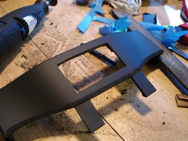
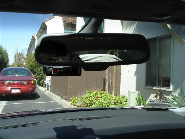
3. Remove airbox - see pic
- Disconnect MAF connector
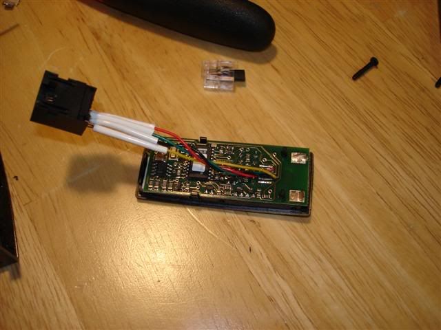
- Disconnect Power Output Stage connectors (see pic - 1)
- Disconnect Solenoid Valve for Wastegate Bypass Regulator Valve connector (see pic - 2)
- Disconnect EVAP canister purge regulator valve connector (see pic - 3)
- Disconnect hoses
- Pull airbox out
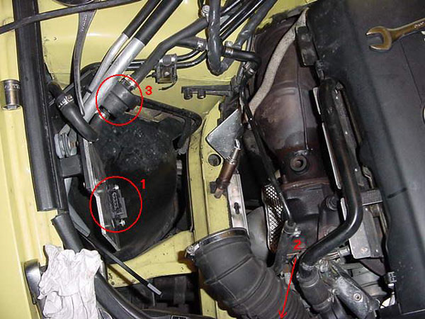
My car has a custom cone air setup, which is why the POS is mounted on aluminum and bolted to the fender.
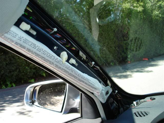
4. Remove coolant tank and set aside
- remove three screws from top (phillips)
- Lift up and disconnect sensor from bottom (careful)
- remove top coolant line and plug.
- Leaving the bottom hose (big hose) connected, rotate the tank around about 135 degrees and lay it down
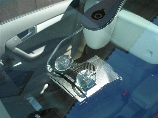
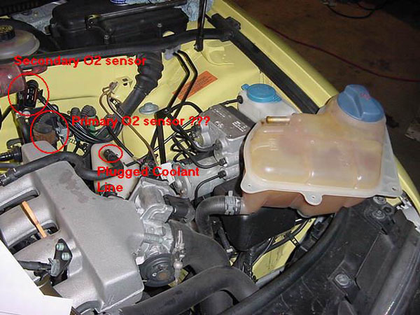 |
| Coolant tank sitting position and O2 sensor connectors. |
5. Disconnect second O2 sensor connector from under the coolant tank (leftmost connector - see pic) and free the wiring from any ties.
6. Remove O2 sensors. The manual does not say to do this, but I did it. Trying to remove the cat is difficult enough without having to worry about breaking the O2 sensors too. Takes a 22mm wrench and a little elbow grease. Youll probably have to track down the connector for the primary O2 sensor, or you might possibly twist the wires enough to break them (mine didnt break, but the jacket/insulator on one wire opened up.)
7. Remove nuts from cat-to-turbo connection. Three 17mm nuts. The shorty wrench will come in handy for the bottom nut.
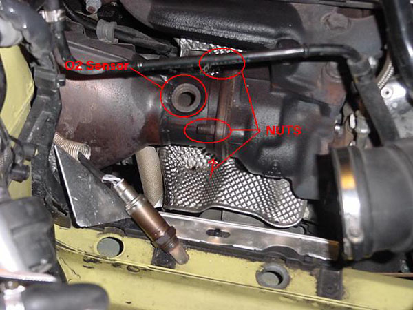 |
| The nuts and O2 sensor have been removed |
8. Remove trans-to-engine bolts that you can get to from above. I think there were three accessible from above (left, middle, and right) 16mm.
9. Remove engine pan/cover from underneath - 10 screws: 3 front, 3 back, 2 in each wheel well.
10. Remove bracket for engine pan/cover - 2 bolts (13mm I think)
11. Jack car up and put on jack stands. Im not really sure of a good place to put the jackstands, I now have two slight dents in the floorboard of my car.
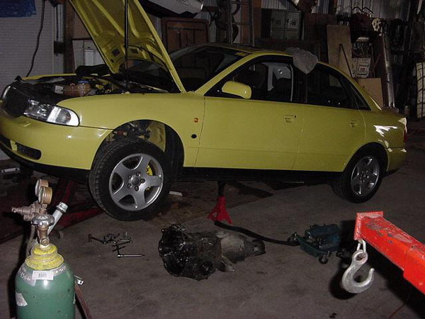 |
| Car up in the air. Possibly bad spot for jack stands. |
12. Remove heatshield from passenger side drive axle. Three 6mm allen bolts, two accessible with an allen socket (left and right) and the top bolt requires an allen wrench.
13. With the car supported on jack stands, place slight pressure on the trans with a jack.
14. Unbolt passenger side mount/support (leave mount connected to support) - two 13mm bolts, and three 8mm, again, two accessible with an allen socket (left and right) and the top bolt requires an allen wrench. Also remove the spring mount from the downpipe. You can let the jack pressure off the trans now, it will be fine without.
15. Loosen clamping sleeve on downpipe-to-exhaust connection. Youre supposed to be able to slide the clamping sleeves forward, but I couldnt get it to budge, and ended up pulling the downpipe out of it instead.
16. Remove the cat/downpipe by pulling it out from under the car. I made the mistake of trying to get it out from the top. I did finally get it with a lot of swearing and fidgeting. Oh well.
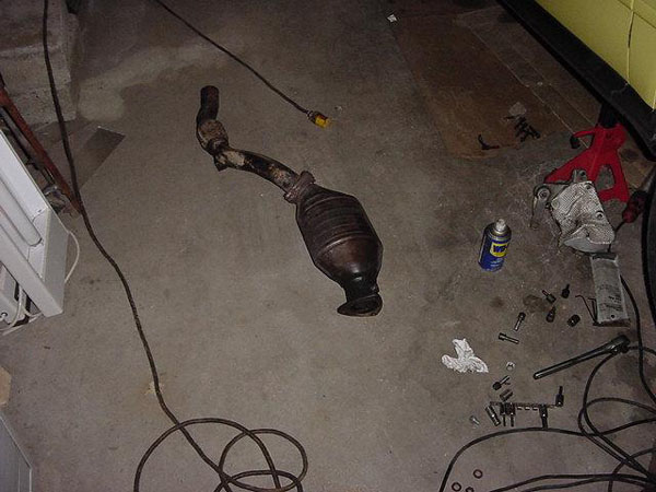 |
| Catalytic converter and downpipe |
17. Remove RPM sensor from transmission. My car did not have this. If it did, it would be located on the drivers side of the transmission, above the flywheel (about the two oclock position if looking at the front of the trans).
18. Now the fun part (1st of many) Disconnect the driveaxles. The shafts are bolted in with six 12 point torx-head bolts. I was able to use a regular 6point T-40 torx bit to remove them, but I highly recommend trying to get the 12 point bit to reduce the chance of rounding one of these things off.
19. Disconnect Speed sensor and reverse light connectors on drivers side of the trans. Make sure no other connectors are attached.
20. Remove starter, two 16mm bolts and one 6mm allen bolt. The wires can stay connected. This can be done one of two ways: The long and painful way, or the short and painful way.
- Long way: Remove bumper, remove A/C belt, remove A/C pump, remove starter.
- Short way: Attempt to get at 6mm allen bolt with an allen wrench by maneuvering your hand and arm through the A/C lines. When finally out (wait until you have to put it back in) remove the two starter bolts, slide the starter forward and attempt to lay it aside somehow.
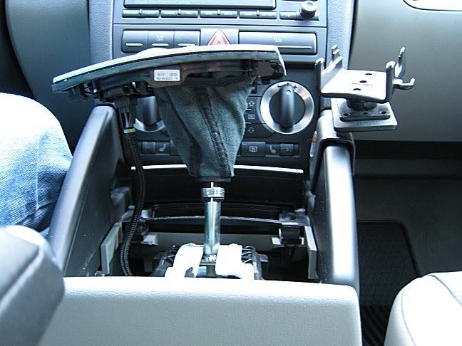
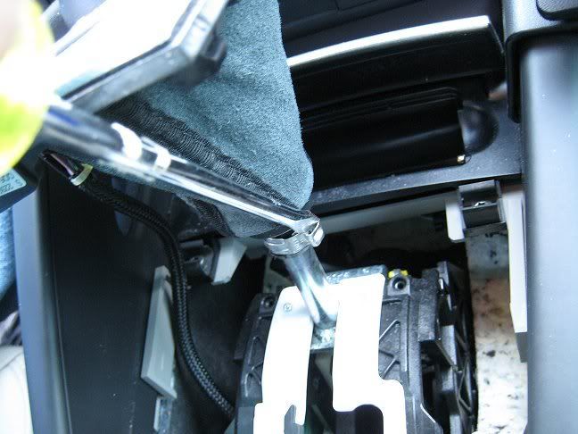
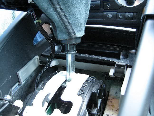
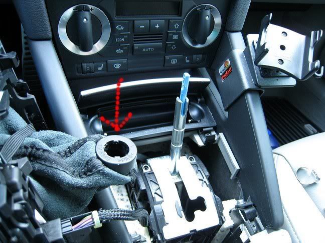
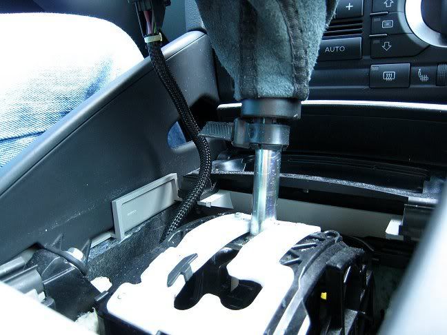
21. Disconnect shift rod, one 10mm bolt
22. Disconnect shift pivot rod - one 8mm (may have been 6mm, not sure) allen bolt. Space is tight requiring the use of an allen wrench. When its out to the point that the allen wrench hits the trans tunnel, remove the allen wrench and try turning the bolt or washer on the backside with your fingers.
23. Remove the heat shield for the driveshaft. My car did not have this.
24. Remove the driveshaft from the trans - six T-40 Torx bits, let it hang on the heat shield.
25. Remove the four engine-to-trans bolts on the bottom (all 16mm), and there should be just two left holding it together afterwards.
26. Place transmission jack under the trans and put pressure on it.
27. Remove drivers side trans mount-to-support bolt (8mm allen bolt), leave the support bolted to the trans.
28. Remove the last two engine-to-trans bolts.
29. slide trans and trans jack back just enough for the bell housing to clear the pressure plate.
30. Lower trans just enough to get access to the clutch slave cylinder. While lowering the trans, DO NOT LET THE INPUT SHAFT HIT THE PRESSURE PLATE "FINGERS" The clutch cylinder is held in with a 6mm allen bolt, and will take a little bit of wiggling to get it out. Careful, its made of plastic. Do NOT remove the line, and do NOT press the clutch pedal.
31. Make sure all drive axles are clear of the trans and lower it. You might have to pull the trans off the jack to slide/drag it out from under the car, or you can just leave it under the car, and slide it out of the way.
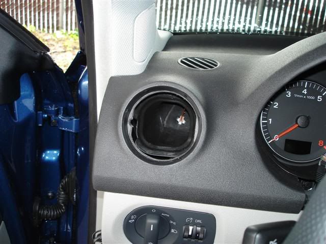
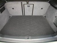
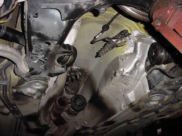 |
| Empty trans tunnel. |
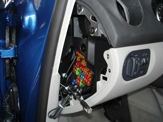
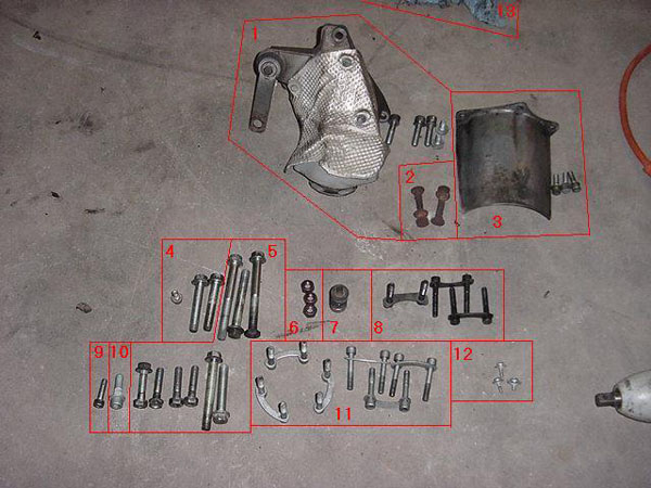 |
| Parts removed |
1 - Passenger side trans mount and related bolts
2 - Exhaust clamp bolts
3 - Passenger side drive axle shield and related bolts
4 - Starter Bolts
5 - Engine-to-Trans bolts
6 - Turbo-to-downpipe nuts
7 - Exhaust hanger spring
8 - Driveshaft bolts
9 - Clutch slave cylinder bolt
10 - Driver side trans support-to-mount bolt
11 - Drive axle bolts
12 - Coolant tank screws
13 - Just a rag, ignore it :)
Removing the clutch/flywheel
1. Remove the six 6mm allen head bolts from the pressure plate and remove it and the clutch plate. A screwdriver might be needed to gently pry it off. Careful, the pressure plate is the only thing holding the clutch plate in, and it WILL fall if youre not paying attention.
2. Bust out the impact wrench to loosen the six 17mm flywheel bolts. You probably dont need the impact, but you will spend a very long time trying to get the bolts loose without one.
Installing the clutch/flywheel
1. Look at the flywheel and youll notice the bolt holes are irregular. The flywheel only goes on one way. when you have all 6 bolts in, torque them down. I held a screwdriver between a flywheel tooth and the block while tightening. The manual calls for 44 ft lbs + 90 degrees. The shorter bolts for the new flywheel probably dont require the 90 degree turn. Check with APR to be sure.
2. Put the clutch disk and pressure plate on, the clutch disk has to go in a certain way (the taller middle side goes towards the pressure plate) Start putting the bolts in, but dont tighten yet. You need to center the clutch disk in the pressure plate. I eyeballed it since I didnt have the alignment tool. Torque the bolts in stages in a triangular fashion when its centered.
Time it took me to get this far, about 7 hours.
Take a break, the hardest part is about to begin.....
1. With the transmission on the transjack (if it has an angle adjuster, make sure its on the correct side), slowly lift it into place, making sure that nothing is in its way. You will need to match the angle of the engine with the angle of the jack. You will have to slide the trans in a little, jack it up, slide it in, jack it up, etc until the trans is aligned withe the engine. It may help to have a greater angle on the trans, and when its lined up, equal the angles out. DO NOT LET THE INPUT SHAFT HIT THE PRESSURE PLATE FINGERS. If one of them bends, bad things happen.
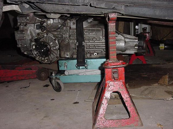 |
| Jack on transjack - notice the the dents from the jackstands. |
2. Put the clutch slave cylinder back on. Trust me on this one, do it now, before the trans is connected.
3. Now the fun part, inserting the trans. Mine slid right in, but if it doesnt, remember patience is the key. Put the trans in gear and try rotating the driveshaft end. this rotates the input shaft, and may help align it. If all else fails, pull the trans out (careful if the slave cylinder is bolted on), and check to make sure the clutch is still centered.
4. The trans probably wont slide all the way in. Get it in enough to get a bolt started on either side (start with the bolts that go through the guide pins.
5. Basically, everything else is the opposite of removal, just a little more difficult.
Reassembly time, about 8 hours.
Things to avoid (aka what I did wrong)
1. Remove the cat/downpipe from the bottom. It will come out from the top with a lot of struggling, yanking, and cursing, or it will drop right out the bottom with slight maneuvering.
2. when putting the transmission in, I got the shifter pivot arm caught between the trans and the hull, and bent it straight. I found this out after I had everything in, and realized I couldnt shift into 1st, 3rd, or 5th. The shift rod wouldnt come back far enough because it hit the shifter pivot arm. A jack and a 2ft long 2x4 promptly bent the arm back into shape :)
3. I tried to put the clutch slave cylinder on after the trans was installed. I could not get it to compress enough to install. I had to crack open the bleed screw and then push it in (I had a hose and container hooked up to catch the fluid), and then bled the clutch system afterwards (not a big deal though)
4. My APR flywheel/clutch was used and didnt have any bolts with it. I had to cut 5/8" off the end of the flywheel bolts in order to use them.
Notes/Comments/Suggestions:
Plan on a weekend for this job. Start Friday night, and if all goes well, you should be done Saturday night, or Sunday morning.
I started Thursday night about 10pm, worked until the trans was out at 4am. I started again Friday night about 9pm, worked until 4am and finished up a couple little things Saturday afternoon.
I should also say that my clutch and center Torsion were replaced about 10 months ago (25K miles) so I didnt have any stubborn bolts.
You might want to start by trying to bust the driveaxle and driveshaft bolts loose first. These will probably be the toughest bolts to get out. If you cant get them out, theres no sense in continuing, and it would suck to have to put everything back together
Some tips in case of a stubborn torx bolt:
1. hit it with a hammer a couple times
2. If it rounds off inside, try pounding an allen bit into it.
3. You could try grinding a slot in it, and using a screwdriver.
4. Try Vise Grips
5. Youll notice that there is a connector between pairs of bolts. If its the right bolt of the pair, you can use this connector as a lever (assuming the left bolt is out of course)