2011 Ford Focus Owners Manual Pdf - The suspension was blended with a very slick by Ford. Feel it, though gentle as you walk slowly, but no one bit unsteady phenomena when the car accelerated at extreme speeds.Dikecepatan high cornering, or spontaneously change lanes on the highway, all easily diladeni the Ford Focus TDCI.
 |
| Google Images |
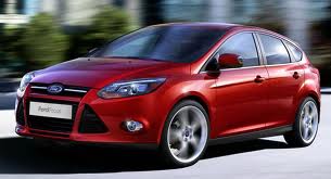
Ford seems no need to dress to make it look sporty Ford Focus. The interface is far from sporty, but the addition of a little body kit on TDCI Type SA / T is making looks more males.
Cabin space looks very attractive. In addition there are many futuristic instrument panel, touch aluminum accents on the steering wheel, gear lever and trim, making the cabin a sporty and elegant appearance.
What is lacking in the features offered on the Ford Focus diesel S type this? Complete! Starting from the comforts such as rain-sensing wipers, auto-dimming rear view mirror and auto on / off headlamps.
Setting the driver and front passenger seat also electrically. Focus has also been equipped with dual zone auto air conditioning settings, as well as Audio and Multi Information Display complete. Intelligent Protection System, ABS, EBD also has become a mandatory tool was embedded in the Focus TDCI S type this.
Ford Focus also offers a distinctive sensation of driving a sporty car Rally. Noticeably from a seated position on an ergonomic seats, a broad view of the future, and all the instrument panels that are easily affordable.
Cabin space is quite tight especially combined with the boom of the 6 speaker audio system its very entertaining. Even from inside the cabin, you will not feel that this is a diesel-engined car.
While it is, of outside the diesel engine sounds rough, rougher than diesel engines Ford Everest though.
Advantage of the Ford Focus which has been in existence in the world rally, one of which is handlingnya very sharp and precise. As if to placate the drivers car, according invited to anything!
Here 2011 Ford Focus Owners Manual